Topology
Once you open a project with gonetem-console, you can modify the topology
with the command edit.
An empty topology looks like that :
nodes:
links:
bridges:
The content of each section is explained below.
Nodes
In the section nodes, you can add host/server/router/switch in the topology.
At minimum, each node is identified by :
a name
a type
These 2 information are declared like that :
nodes:
  host_name:
    type: docker.host
  router_name:
    type: docker.router
  switch_name:
    type: ovs
2 main types of node are available in gonetem :
docker node declared with the type
docker.<type>switch declared with the type
ovs
More details are given below for each type of node.
Docker node
A docker node is a container launch by gonetem. Bydefault, 3 kinds of docker node are available, each one associated to an image defined in the server configuration file. These one ared by default:
mroy31/gonetem-host identified by the type docker.host, which emulates a terminal node
mroy31/gonetem-server identified by the type docker.server, which emulates a server node (with http, tftp and dhcp server for now)
mroy31/gonetem-frr identified by the type docker.router, which emulates router based on the software FRR
All these images are available on docker hub. It is also possible to use a custom image
thanks to the options image (see below). You can also defined new kind of
node in the server configration file. See Docker nodes configuration for more details.
Options
- Several options are available when you declare a docker node:
launch(boolean, optional): set to no to not start the node at the launch of the project (yes by default)ipv6(boolean, optional): set to yes if you want to enable ipv6 support on this node (no by default)mpls(boolean, optional): set to yes to enable mpls support on this node (no by default).image(string, optional): set to provide a custom docker image for this nodevolumes(string list, optional): Allow to bind host path in container filesystem (like -v option indocker run`). The syntax is/host/path:/container/path
VRF support
To facilitate the implementation of L3VPN with gonetem and FRR, it is possible to instantiate linux VRFs at the launch of FRR router.
For that, you just need to declare list of VRF in the vrfs parameter.
VRRP support
- FRR supports VRRP protocol. However, its implementation requires some prerequisite to work.
The creation of a macvlan interface with the correct MAC/IP adresses for each VRRP group
To facilitate the use of this protocol, gonetem support the parameter vrrps for docker.router nodes, for vrrp configuration.
This parameter take a list of object with the following attributes :
interface (int): physical interface id used for VRRP
group (int): VRFRP group id
address (string): VRRP IPv4 address
Connection to the management network
Gonetem offers the possibility to create a network dedicated to the docker nodes management.
This network allows to access docker nodes from the host OS throught a bridge.
To connect to this network, you need to use the parameter mgnt, that contains the following sub-parameters:
enable (bool): set to yes to connect the node to management network
address (string): IPv4 address used to access to this node
See section dedicated to management network configuration for futher details.
Example of docker node
nodes:
  R1:
    type: docker.router
    ipv6: yes
    mpls: yes
    volumes:
    - /tmp:/tmp
    vrfs: [VRFA, VRFB]
    vrrps:
    - interface: 0
      group: 1
      address: 192.168.1.252/24
    mgnt:
      enable: yes
      address: 192.168.0.1/24
Extra : init script
For specific situations, it is possible to include an init script in docker node.
The path is /gonetem-init.sh. If this file exits, it is saved in the .gnet project file and executed at the launch of the node.
Switches
In gonetem, switch is a node like any other. You just need to use the
type ovs. In background, OpenVSwitch is
used to emulate it. A docker container based on mroy31/gonetem-ovs
is launched for each project. All switches are instantiated in this container.
Example of switch nodes
nodes:
  sw1:
    type: ovs
  sw2:
    type: ovs
When you launch a console on a switch, a custom prompt appears allowing basic commands on the switch (for now, vlan and bonding configuration). For more details on available commands, see here.
Links
In gonetem, links between nodes are defined in the links. Each link
definition requires the following parameters:
peer1(string, required): left connection of the link, following the format<node_name>.<if_number>
peer2(string, required): right connection of the link, following the format<node_name>.<if_number>
delay(int, optional): bidirectionnal delay on the link in ms
jitter(int, optional): bidirectionnal jitter on the link in ms
loss(float, optional): bidirectionnal loss on the link in percent (between 0.0 and 100.0)
rate(int, optional): bidirectionnal link rate in kbits per second
buffer(float, optional): bidirectionnal buffer size (equivalent tolimitparam in thetccommand). The value has to be set in BDP (Bandwith Delay Product) scale factor (1.0 per default).
peer1qos: optional section to configure link QoS in the direction peer1 –> peer2. This section accept the same parameters than global configuration (ie. delay/jitter/loss/rate/buffer)
peer2qos: optional section to configure link QoS in the direction peer2 –> peer1. This section accept the same parameters than global configuration (ie. delay/jitter/loss/rate/buffer)
nodes:
  host:
    type: docker.host
  sw:
    type: ovs
  R1:
    type: docker.router
links:
  - peer1: host.0
    peer2: sw.0
    loss: 2
  - peer1: R1.0
    peer2: sw.1
    delay: 100 # ms
    jitter: 10 # ms
    rate: 1024 # 1Mbps
nodes:
  host:
    type: docker.host
  sw:
    type: ovs
  R1:
    type: docker.router
links:
  - peer1: host.0
    peer2: sw.0
  - peer1: R1.0
    peer2: sw.1
    peer1qos:
      delay: 100 # ms
      jitter: 10 # ms
      rate: 1024 # 1Mbps
    peer2qos:
      delay: 200 # ms
      jitter: 20 # ms
      rate: 2048 # 2Mbps
Bridges
In the bridges: section, you can add some bridges to the topology.
A bridge should be declared if you want to communicate with the host network.
A bridge takes 2 arguments:
host(string, required): the name of the host interface that will be connected to that bridge
interfaces(list, required): list of node interfaces connected to this bridge
Example
bridges:
  my_br:
    host: eth0
    interfaces: [R1.0, host.0]
Management network configuration
You can add a dedicated management network in the topology definition. It allows you to SSH or otherwise access nodes directly from the host OS throught a dedicated bridge.
To activate this feature, you have to:
Declare the parameter
mgntnetwith the following options:
enable (bool): set to yes to activate management network
address (string): IPv4 address on the host side used to access nodes
Connect nodes to the management network, thanks to the parameter
mgntin the node configuration.
Make sure the specified IP addresses are in the same subnet and do not conflict with other networks on your system.
Example
nodes:
  host1:
    type: docker.host
    mgnt:
      enable: yes
      address: 192.168.0.1/24
  host2:
    type: docker.host
    mgnt:
      enable: yes
      address: 192.168.0.2/24
mgntnet:
  enable: yes
  address: 192.168.0.254/24
Full example
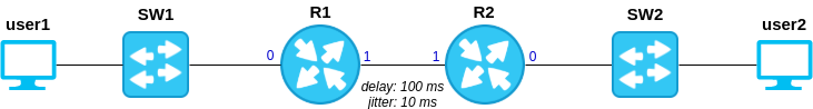
Below, you will find topology file to create the network above:
nodes:
  user1:
    type: docker.host
  user2:
    type: docker.host
  sw1:
    type: ovs
  sw2:
    type: ovs
  R1:
    type: docker.router
  R2:
    type: docker.router
links:
  - peer1: user1.0
    peer2: sw1.0
  - peer1: sw1.1
    peer2: R1.0
  - peer1: R1.1
    peer2: R2.1
    delay: 100
    jitter: 10
  - peer1: R2.0
    peer2: sw2.0
  - peer1: sw2.1
    peer2: user2.0